

R&D LAB Computational Design Shipped Teaching instrument
Mechanism Lab
Sixty mechanisms across ten chapters, each driven by exact kinematics, each reporting numbers that are true of what is drawn.
- 60mechanisms
- 10chapters
- 6fields per derivation
- 1render rig for all sixty
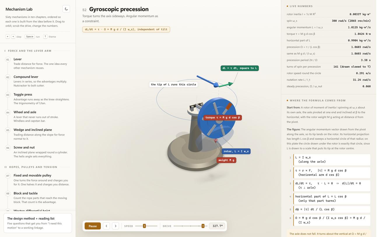
Entry 52, gyroscopic precession. The panel computes the precession twice, once as torque over L cos beta and once as M g d over I omega, and gets 1.8603 rad/s both times.
Why this is published
An animation can be faked. Exact kinematics cannot. Mechanism Lab is our proof that we model machines as equations first and pictures second, which is the same discipline a facade, a nesting layout or a parametric assembly demands.
Most mechanism references show a moving picture and a formula, and quietly leave a gap between them. This one closes the gap: every part is placed by solving the mechanism, every number in the panel is measured off that solution, and every entry ends with a derivation showing how a person could have arrived at it from first principles.
Why a deadbeat escapement does not kick back
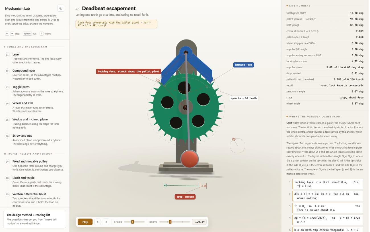
Entry 45. While a tooth rests on the locking face, the escape wheel must not move. Write the locking face in polar coordinates about the anchor pivot and ask what shape leaves a resting tooth exactly where it is, and one possibility survives: the face has to be an arc about that pivot. Which is why the row labelled recoil carries no number but a sentence: none, the lock face is concentric.
The other rows are the price. The tooth pitch is 12.00 degrees and one step of the wheel is 6.00. Of that, 5.09 degrees go to the pendulum as impulse and 0.91 degrees are drop, and wasted. The two add back up to the step, and moving the half span off 45 degrees moves the split with it.
The shape of it
How a derivation is built here
- 01 Start from One sentence about what is not allowed to happen. For the escapement: while a tooth rests, the wheel must not move. For the lever: a rigid beam does not bend, so both ends share one angle.
- 02 The figure The picture that settles the question, written out. For the lever it is two similar right-angled triangles sharing their angle at the fulcrum. Without this paragraph the algebra below it is conjuring.
- 03 The algebra Numbered lines, each with its reason in brackets beside it. Only equations belong in this field; prose set in monospace was one of the faults taken back out.
- 04 The result The formula printed under the title, and beside it the price. For the lever: nothing is created, the load travels a over b times less far than the effort.
- 05 The leap How anyone thought of it at all. For the lever: Archimedes proved it without measuring a single force, from symmetry alone, by splitting one weight and sliding the halves apart by equal amounts.
- 06 The history When and where it first appears, deliberately kept apart from the derivation. A name is not an argument and a date explains nothing.
An escapement running, then a switch
The decision
Tie the readout to the solve, then live with it
The easy build would have been to animate the geometry and write the numbers beside it. Instead every entry is solved per frame and every row in the panel is a measurement off that solution. It costs more, and it has a consequence you have to accept: the application contradicts itself visibly the moment something is wrong.
Entry 24, belt and sprocket, shows it on a detail. Centre distance wanted, 4.000. Centre distance built, 3.953. The gap exists because the belt teeth have to be a whole number and 49 is the nearest one. The panel prints both figures rather than printing the wanted one and drawing the other.
Entry 16, the over-centre clamp, goes further. With the clamp open there is no clamping force, and the mechanical advantage row does not read zero, it reads: not in contact. A number there would be an invention. Entry 52 says the matching thing about its own drawing: 161 turns of spin per precession, drawn slowed to 7.
The most expensive fault of this design was invisible. Force arrows were normalised to the largest force in the set, so the drawing at 20 newtons was byte for byte the drawing at 400. The slider moved the readouts and nothing else, which is exactly why that survives a quick review. Force arrows now run through an absolute scale with a fixed reference.
An animation can be faked. A readout that comes out of the same arithmetic as the picture can only be wrong together with the picture.
Through the curriculum
Five entries from five chapters
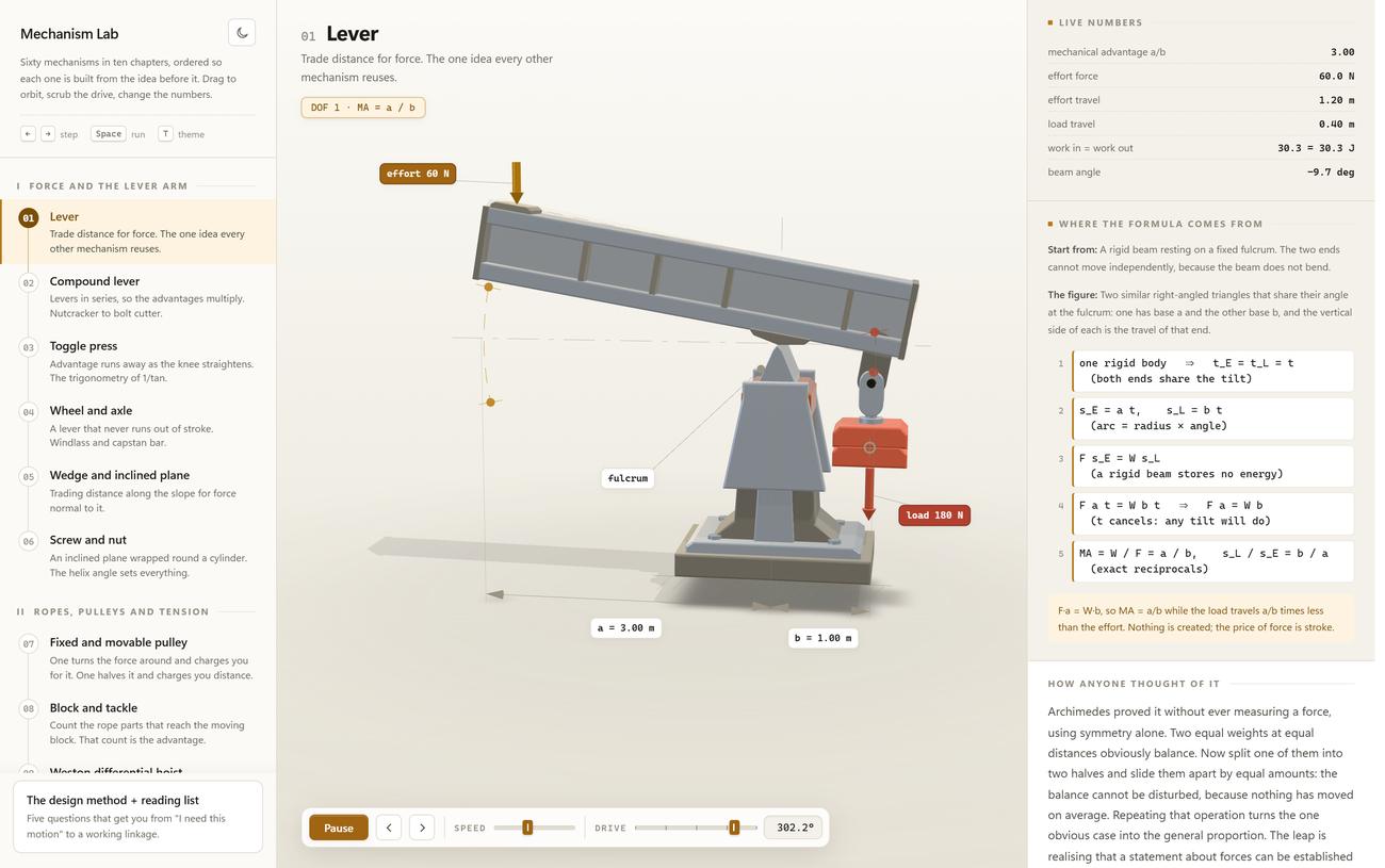
01 LeverChapter I. Advantage 3.00 out of a equals 3.00 metres and b equals 1.00 metre, effort 60 newtons against a load of 180, and a row that sets work in beside work out.
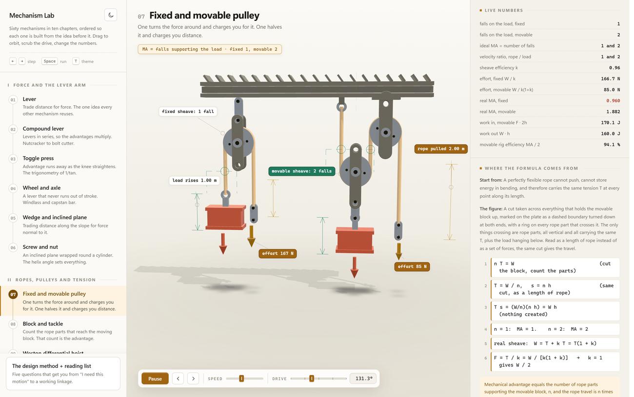
07 Fixed and movable pulleyChapter II. Ideal 1 and 2, real 0.960 and 1.882, because each sheave is costed at an efficiency of 0.96. The fixed pulley is printed in red: it costs more than it returns, and turns the force around in exchange.
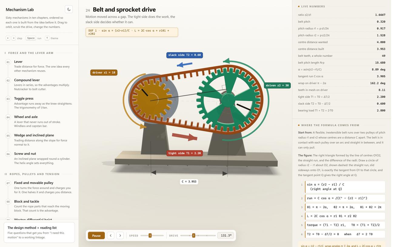
24 Belt and sprocket driveChapter IV. Ratio 1.6667 from 18 and 30 teeth, 162.2 degrees of wrap on the driver, 8.11 teeth in mesh. The built centre distance of 3.953 stands next to the wanted 4.000.
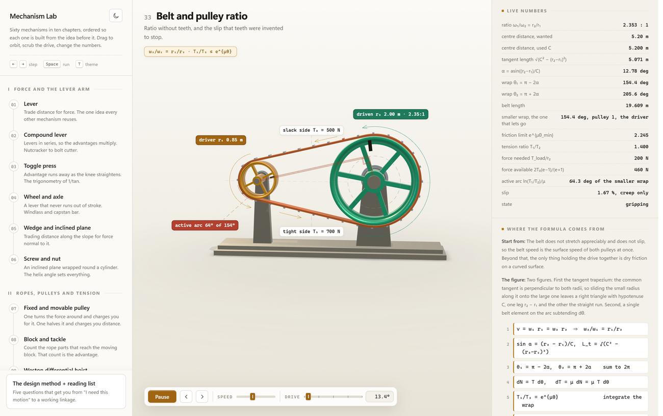
33 Belt and pulley ratioChapter VI. With no teeth, only friction holds. The limit e to the mu theta is 2.245 against a demanded tension ratio of 1.400: the belt grips, and the 1.67 per cent of slip is creep only.
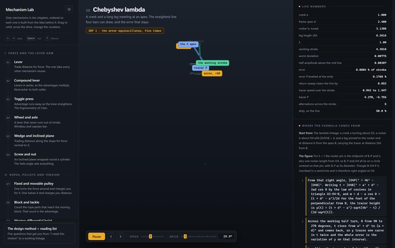
58 Chebyshev lambda, darkChapter X, in the second theme. The error alternates five times between its extremes and stays at 0.0884 per cent of the stroke. Level the reference line through the end points instead and it becomes 0.1768 per cent, exactly twice as large.
How an entry is built
One kinematic solve feeds everything on screen
- Link lengthsparameters
- Drive angleuser input
- 3D geometryplaced, not posed
- Calloutsanchored to points
- Live numbersmeasured off the solve
- Derivationthe same symbols
No entry stores a keyframe or a rendered image. The geometry, the callouts, the readouts and the derivation all read from the same solved state, which is why they cannot drift apart.
When the honest answer is not a number
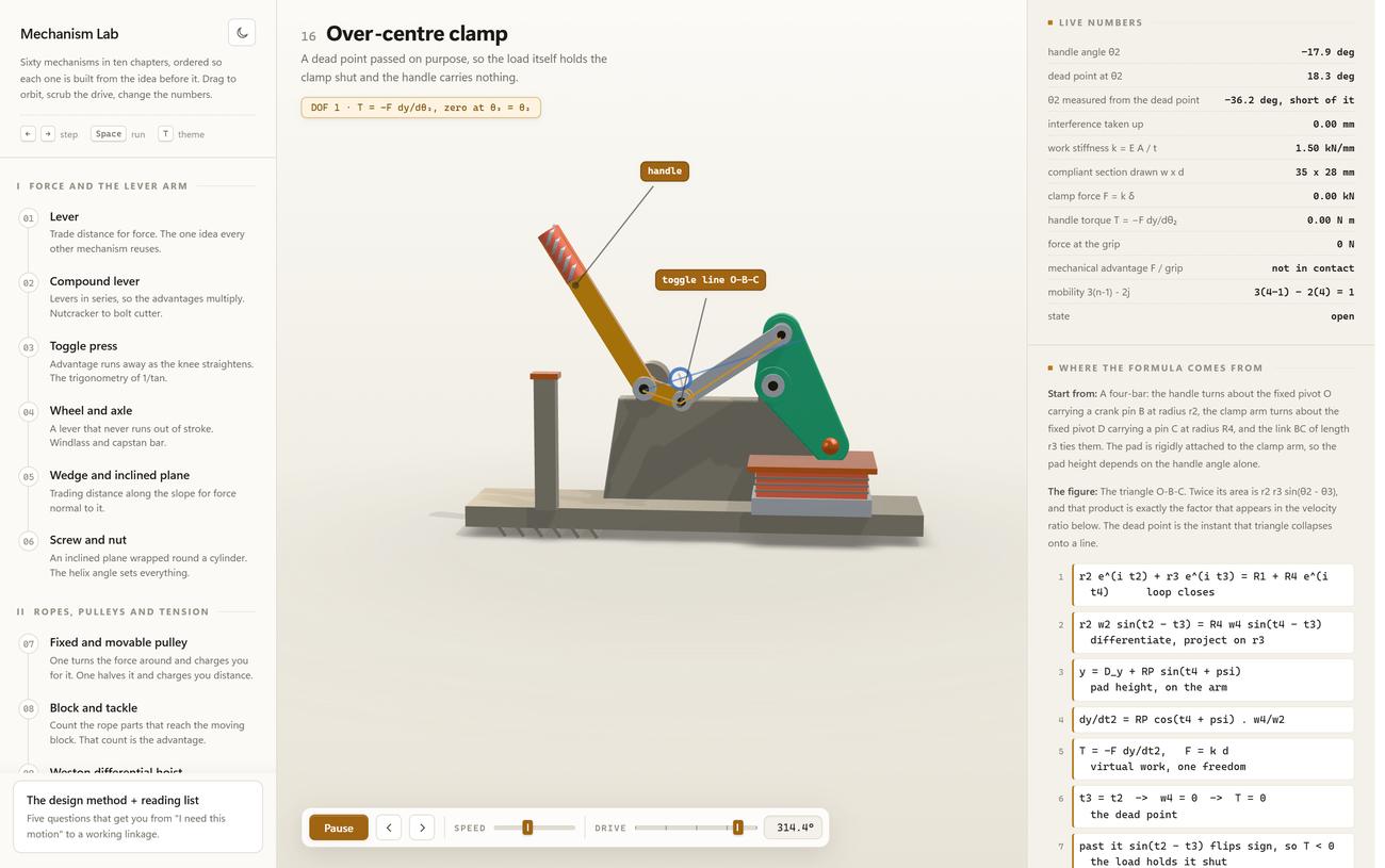
Entry 16 standing open. The handle angle is at minus 17.9 degrees, the dead point is at 18.3, and the panel works out the difference for you: 36.2 degrees short of it. Clamp force 0.00 kilonewtons, handle torque 0.00 newton metres, interference taken up 0.00 millimetres.
Mobility is printed as a calculation rather than as a claim: 3 times 4 minus 1, less 2 times 4, is 1. Four links, four pin joints, one degree of freedom. Pull the handle past the dead point and the sign of the torque flips, and from there the load holds the clamp shut instead of opening it. Which is the entire purpose of the part.
Under the hood
Where it fits
- Manufacturers explaining a moving product to a buyer who will never read a drawing.
- Engineering teams that need a shared vocabulary before a design review, not after it.
- Training and onboarding where the wrong mental model is expensive to correct later.
- Any brief where the honest answer is a mechanism and the usual answer is a video.
Image credits: every frame on this page is a screenshot of our own application.
“What I cannot create, I do not understand.”
Why this is published
What this means for your project
More from the lab
 Method Event Scout A language model reads the event pages; everything else is fixed code. What remains is a short list of where a day in person is worth it.
  Applied Research Vellum Edges, perspective, light and text are all worked out on the phone. A document leaves the device only when someone sends it.
 Have a product that only makes sense when it moves? We can make that legible.
Get in touch